
Webweasel's first SDR
The softrock lite II - Webweasels first experience with software defined radio
Software defined radios are great fun, having the ability to see the demodulated waterfall is fantastic. Once I had seen the waterfall I had to have one. But the pre-built SDR's are expensive so I looked into SDR kits. I mean how hard can it be?
I was quite intimidated by some of the full range kits, with no soldering experience I did not want to outlay a lot of money for something I had no idea how to build or diagnose faults for. Then I came across the small cheap fixed frequency SDR kits that are available from many different websites. For the small outlay, I could take my time learning how to solder electronic componants without worrying to much about the cost. So I took the plunge and ordered myself a SOFTROCK Lite II kit from KB9YIG.com. The kit cost $20 which converted into £14 including delivery to the UK. It comes with 5 different crystal's one for each of the 20m, 30m, 40m, 80m, 160m bands giving a great choice. I went for the 80m band.
The kit arrived very quickly considering it was coming from the us and fits in a padded envelope, so no worries about being home to collect a parcel. I had to buy myself a soldering iron of course, but this would be an investment for future projects. I also picked up a third hand with a magnifying glass, a multimeter, some solder and some solderflux from my local Maplin.
I opened out the kit and had a look at what I was up against:
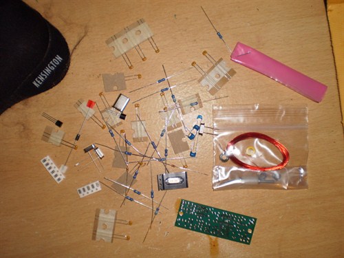
Hey this doesent look too bad, wait where are the chips? Whats in this little pink bag?
.......
Ohhhhh. I might be in trouble now. These things are tiny!
Suddenly it looked a lot more difficult and I began to have second thoughts about being able to do this. But hey, this is why I bought the $20 and not the expensive full range SDR kit. This will be a learning experience, I'll probably screw it up, but I'll learn from doing, so lets give this a try. First I decided to watch some videos on how to solder. So the general advice I can give you is read this article "How to solder like a pro" and this video on soldering surface mount chips.
As with all projects like this preperation is key, so I read through the guide to constructing the softrock and prepared my work surface and everything I need.
Preperation
Preperaton list:
- Softrock Lite II kit
- Soldering Iron
- Lead free solder
- Solder flux
- Third hand with magnifying glass
- A baking tray
- A soldering iron stand
- A bright desklamp
- Angle nose tweezers
- Grounding strap
The baking tray and desklamp might be a bit of a suprise on the list, but both are essential items. The electronic components you work with range from small to tiny, if you sneeze the baking tray might save some of those tiny components from flying off your desk. The lamp is also a must, I cannot overemphazise how important having a good source of light is, normal room light is not enough to be able to see the tiny things you will be soldering. You also need to be able to see the markings on the chips to get them the right way around. You really want to avoid soldering a chip in place only to find it is upside down.
I had hoped to solder the resistors and other easier parts in place first to get some practice in but reading the guide it became obvious that the surface mount chips needed to go on first as putting them on last would be much more difficult with the other components in place. So I bit the bullet and started soldering.
Soldering the surface mount chips
Soldering the surface mount chips should be done in a static free environment. Ideally this would consist of a grounded static mat with a wrist strap (which I use as an ankle strap instead, its annoying to have one hand restricted by a spring cable and the cable is attached with a popper, so if I walk away it snaps off. This does of course mean I have been caught in public with a grounding strap around my ankle, which can lead to awkward questions). As I am a computer technician in my real life job, I have these already. At a minimum you need to ground yourself to earth before working with these chips.
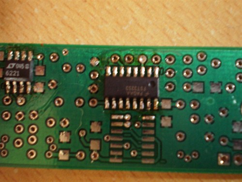
There are 3 surface mount chips for the softrock lite II kit and as you will see in the picture that follows, they must go on in the right order or it will be very difficult to add one of the chips. So I clamped the board in place, and orientated the chip. The board has a 1 mark next to the position for pin one of the chip and the chips themselves are marked in several different ways. You can indentify pin one by one of the following:
- A printed 1 next to pin 1
- A circle divot in the chip next to pin 1
- A bevelled edge to the chip (i.e. one edge has a slant)
I aligned the chip as carefully as I could (this is a tweezers job) and applied solder flux all around the chip. Now I have some experience with soldering I can offer the following advice: You can almost never use too much flux. Solder flux will make the difference between an easy and quick solder joint and a bad one. Always remember to flux. Before attempting to apply solder you want to be sure the chip won't move if you knock it by accident so you tack the corners first. To do this you simply apply the soldering iron to the solder pad at each corner leg of the chip. The solder will melt and bind that leg to the pad. Tacking all 4 corner legs should be enough to make sure the chip won't move. Its worth giving it a small push with the tweezers to be sure.
I then applied the solder to the legs as shown in the video just very quickly melting the solder and pulling the tip away. I was suprised at how naturally the solder flowed up the leg and was very pleased with my results:
The main build
With the chips in place I moved on to the next stages of the build. I found the next stage a great way to learn electronics having never studied the topic before. The circuit consists of separate parts that are built and tested as you go.
It consists of the following build stages:
- Build and Test the Power Supply Stage
- Build and Test the Local Oscillator Stage
- Build and Test the Divider Stage
- Build and Test the Operational Amplifiers Stage
- Build and Test the Band Pass Filter Stage
- Build and Test the Mixer Stage
- Build and Test the External Connections Stage
The build instructions are great for a novice like myself, but every now and then the author writes in a way that takes existing knowledge to understand. He gives helpful advice on identifying components such as reading resistor band colours and identifying the capacitors but occasionally does not fully explain a concept and it took a little thinking about how things were supposed to work. I was a little unsure about winding the toroids for the band pass filter and had to sit and think about how a transformer works before I could understand if my connections were correct. This however is more a reflection on my own ignorance of electronics rather than the build instructions, which are excellent. Soldering the majority of the components was simple enough, but you have to be very careful to get things the correct way round. The term measure twice, cut once applies here. Check twice you have the right component and that it is in its correct holes and the right way round. Don't solder unless your sure. Desoldering a component over a mistake like that is frustrating and also risks destroying the component.
I found the trick to soldering was to use flux, as mentioned before and also to make sure I had a small blob of fresh solder on the tip of my iron. It needs to be just enough to contact the componant being soldered, it should not wrap around it. The small blob will greatly assist in transferring heat to the component as is essential to making a good solder joint. A dry soldering iron tip will not get the leg hot enough and the solder will not melt, but the heat will flow up the leg of the component and possibly damage it. With the small blob on your iron tip, the leg will get to the right temperature and the solder will melt and flow nicely.
Half way through
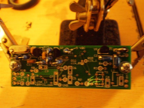
It is important to make sure the frequency specific componants are selected correctly as you go through the build. Several of the stages have specific parts to them so make sure your using the right ones. I found the surface mount capacitors the most difficult parts to mount but overall I was pleased with the final results.
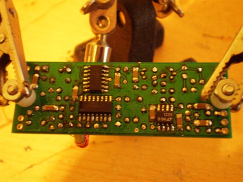
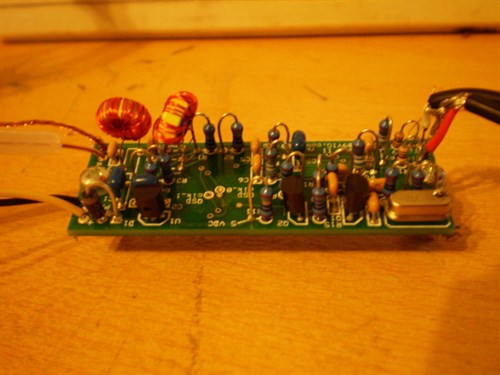
Finished bottom side
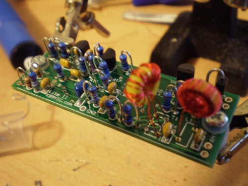
Winding the toroids
The bandpass filter stage was very tricky and I found winding the coil and transformer particular frustrating. Its a very fiddly job and took me several hours before I had something "Good enough" but I do intend to redo these at a later date. Stripping the enamel off of the wire used is very annoying and the wire can break if you get it too hot. It's rather frustrating to wind a toroid and then have the wire snap too short on you. The key again is flux, coat the enamel in flux and then strip it with a large drop of solder on your iron, run it up and down the area to be stripped and the enamel should melt and come away leaving the tinned wire. By the third time I had messed this up, I decided to play it safe, so my coil and transformer stick up a little!
Almost complete
Final stage
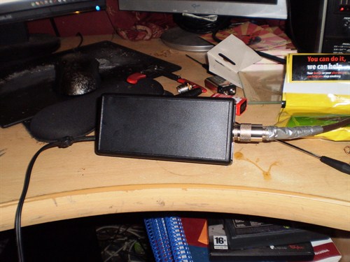
The final stage is to connect the external connectors and test the build. You need a stereo headphone cable with a male jack to plug into your soundcard, a power connector and your antenna. I decided to use a 9V battery to power this board so picked up a lead and a audio cable from Maplin. I also picked up a small project box to keep the board in which had a 9V battery slot and a UHF coax connector for the antenna.
The complete board
Now the moment of truth. Did it work? Lets apply some power and see if anything goes pop....I clipped on the battery and watched the chips too see if the magic smoke would escape. Nothing happened. Wow it didn't go pop! OK great, thats a good sign. I disconnected the battery, plugged the audio cable into my pc and started WinradHD. OK lets see... I applied the battery again and a loud pop came over the speakers well, I guess that means its sending out audio. Nothing appeared on the waterfall. Lets apply the antenna:
Plug in the antenna
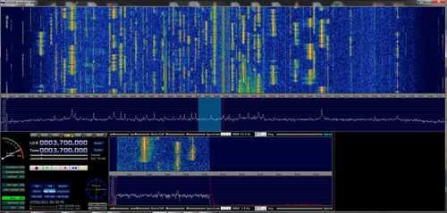
Straight away several morse streams poured through my speakers. It worked! Success! Ha ha! I sat there holding the two strands of wire for the antenna to the plug of my dipole with a grin on my face. I had not expected it to work, but to ruin it as I learnt to solder.
Now it was time to put it in a proper box and make it usable without being a loose circuit board. I drilled a hole in the project box to accept the UHF female plug and another for the audio lead. The plug for the antenna was quickly soldered and I had my build complete.
The finished item
Conclusion
This was a lot of fun! The SDR is fantastic it works just like
it should and reception is great. I have even heard and recorded
s06 on it and listening to number stations is the goal. For the
cost its a fantastic little kit and I recommend it for anyone who
is interested in the SDR experience.